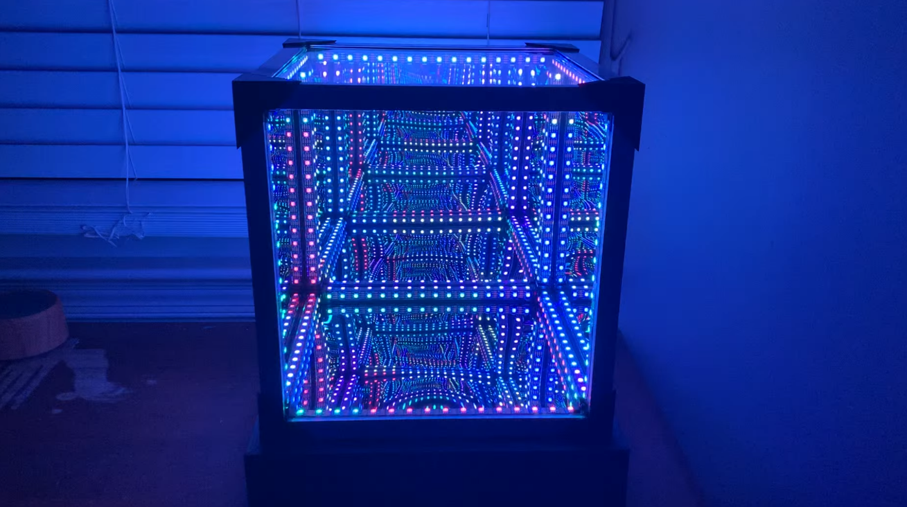
I designed and built this LED Infinity Cube using 3D printed frames, one-way mirror film, and over 300 individually addressable WS2812B LEDs to create a 3D infinity mirror effect. The lighting is fully managed via a custom Bluetooth smartphone controller. The core challenge of the build was managing the high-density electrical routing for the LED strips while keeping the mechanical footprint tight enough to hide the wiring.
Mechanical Design & 3D Printing
I designed the physical structure of the cube in Fusion 360. To get the six mirror faces to align cleanly, I modeled custom 3-axis corner joints, interior mounting brackets, and aluminum trim end-caps to lock the frame together and hide the raw metal edges.
To keep the exterior looking clean, the structural support members also act as wire conduits. I used narrow acrylic tubing to form a rigid backbone that could simultaneously hide the wire routing. Because the space inside the tubes and 3D printed corners was incredibly tight, every wire had to be cut to an exact length to avoid bunching up during final assembly.
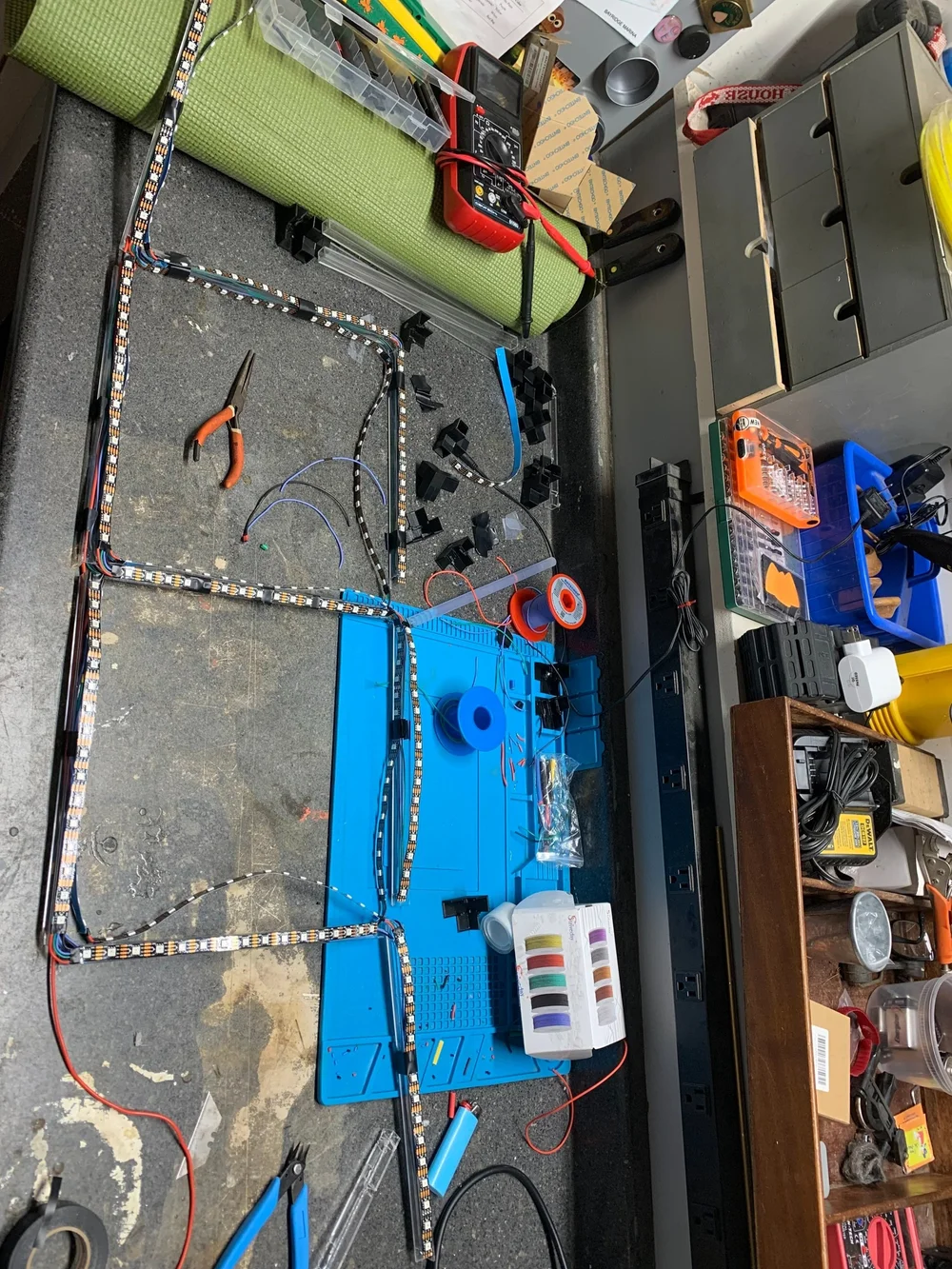
Initial frame assembly showing the 3D printed corner brackets and the acrylic conduit tubes.
Electrical Routing
Wiring over 300 addressable LEDs across a 3D frame required some upfront planning. To keep the dynamic lighting animations smooth and synchronized, I routed the data line as a single continuous path, running in series across every face of the cube.
This meant all the soldered connections had to fit inside the tight 3D printed corner brackets. The wiring had to be low-profile and solid enough to handle the mechanical stress of snapping the final housing together without breaking a connection.
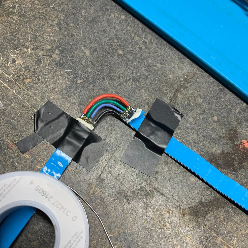
High-density solder joints squeezed into the corner brackets to keep the data and power lines hidden.
Debugging Voltage Drop & Power Injection
During initial bench testing, I ran into a standard WS2812B issue: voltage drop. With a continuous run of 300+ LEDs at full white brightness, the resistance in the strips caused the voltage to sag toward the end of the line. This resulted in the furthest LEDs turning a dim, reddish-orange color because the blue and green diodes weren’t getting enough voltage to turn on fully.
To fix this without capping the overall brightness in software, I added 5V power injection taps to the wiring harness. By running standard power lines directly to intermediate points across the LED matrix, the voltage stayed stable across the entire run, restoring the bright, uniform white color.
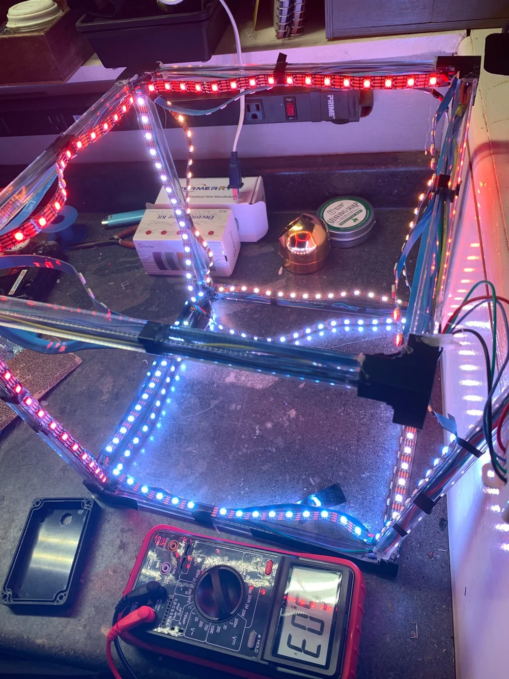
Demonstration of voltage drop: the un-injected LED runs dim and shift orange toward the end of the circuit.
Integrated Base Enclosure
All supporting electronics were housed in a custom-designed base unit situated beneath the cube. The enclosure neatly organizes a high-current 5V DC switching power supply, and a Bluetooth wireless receiver module, ensuring safe wire termination and easy maintenance access while keeping external clutter out of sight.
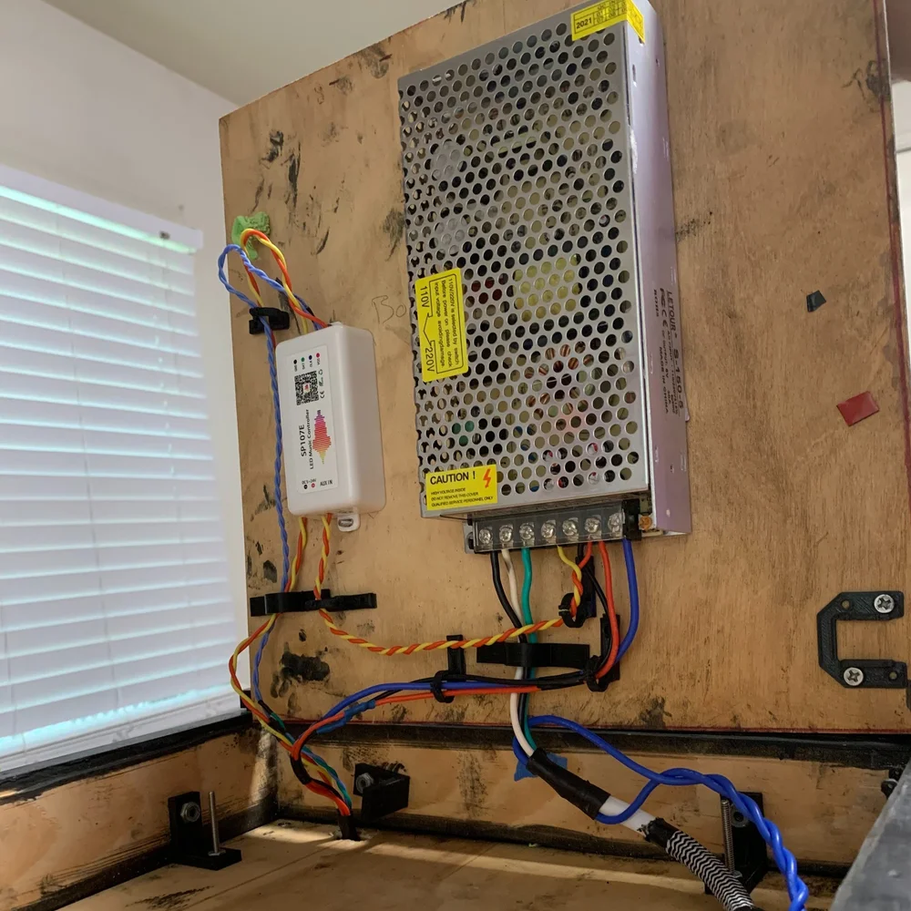
The integrated base enclosure housing the 5V DC power supply and Bluetooth control module.