Getting a robot to make a cup of coffee from start to finish takes a lot of coordination, solid computer vision, and exact kinematics. For this project, I built an autonomous robotic barista workcell inside ROS 2 Humble and Gazebo. The setup runs on a Universal Robots UR10e 6-DOF arm, a Robotiq 2F-140 adaptive gripper, and an Intel RealSense D435 depth camera mounted right on the wrist (eye-in-hand).
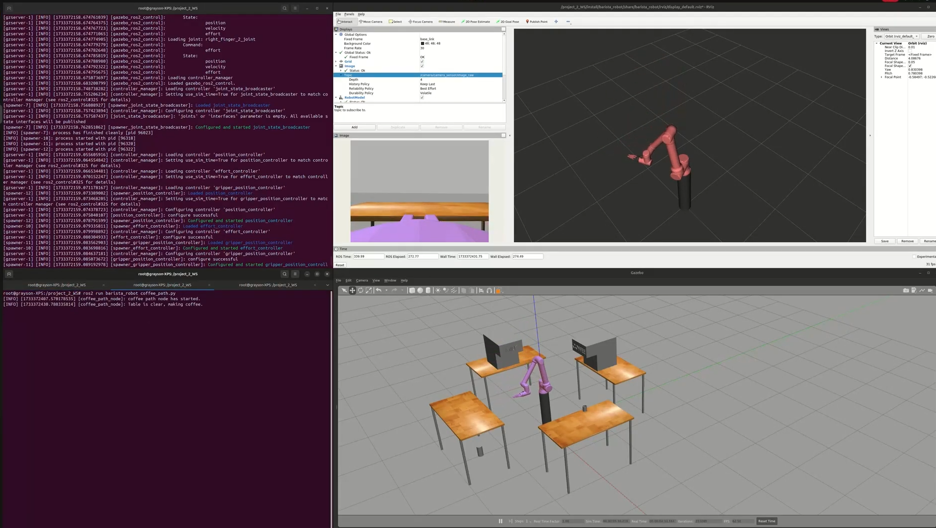
My ROS 2 development setup running synchronously: The Gazebo physics simulation of the 4-station café (bottom-right), RViz 3D model with the RealSense camera feed (top-right), ROS 2 controller logs (top-left), and the coffee_path.py script handling the trajectory sequence (bottom-left).
4-Station Café Workcell Architecture
I designed the workcell in a circle around a central pedestal-mounted UR10e arm. This breaks down the coffee-making process into four specific stations. Every station uses its own ROS 2 action interfaces to sync up the arm’s movements with the dispensing hardware.
- Grabs cups from a vertical gravity-fed dispenser
- Uses the eye-in-hand camera to verify the cup size
- Picks up the cup using the Robotiq gripper's adaptive grasp and slip detection
- Moves into position under the espresso spout
- Holds the cup perfectly steady to prevent spills during extraction
- Handles adding milk and transferring the pitcher
- Moves straight down into the steam wand zone
- Drops the finished drink off at the pickup counter
- Carefully opens the gripper and backs the arm away
- Checks the depth sensor to confirm the table is clear before serving
Kinematic Modeling & Resolved-Rate Cartesian Control
Forward Kinematics
To figure out exactly where the tool frame (tool0) is relative to the robot’s base (base_link), I set up the forward kinematics using standard Denavit-Hartenberg (DH) parameters for all six of the UR10e’s revolute joints.
| Joint $i$ | Link Length $a_i$ (m) | Link Twist $\alpha_i$ (rad) | Link Offset $d_i$ (m) | Joint Variable $\theta_i$ |
|---|---|---|---|---|
| 1 | 0.0000 | $\pi/2$ | 0.1807 | $\theta_1$ (Variable) |
| 2 | -0.6120 | 0.0000 | 0.0000 | $\theta_2$ (Variable) |
| 3 | -0.5723 | 0.0000 | 0.0000 | $\theta_3$ (Variable) |
| 4 | 0.0000 | $\pi/2$ | 0.1742 | $\theta_4$ (Variable) |
| 5 | 0.0000 | $\pi/2$ | 0.1199 | $\theta_5$ (Variable) |
| 6 | 0.0000 | 0.0000 | 0.1166 | $\theta_6$ (Variable) |
Inverse Kinematics & Trajectory Tracking
For actually moving the arm along a Cartesian path, I used resolved-rate motion control. To map the end-effector’s Cartesian velocity back to the joint velocities, we use the geometric Jacobian matrix:
Since we need to calculate the necessary joint velocities to follow the coffee-making trajectories, I inverted the Jacobian using the Moore-Penrose pseudoinverse. This handles any redundant degrees of freedom smoothly:
To run this on the actual controller hardware, I discretized the execution using a standard forward Euler integration step matching the controller’s update loop:
Workspace Optimization
To keep the arm from smashing into the service tables and to avoid kinematic singularities, I restricted the robot’s operational workspace to an upper hemisphere. Given the UR10e’s maximum reach radius of $R = 1.3\text{ m}$, this limits our safe working volume to:
Simulation Dynamics & Singularity Avoidance
Kinematic Singularity Mitigation
When I first started testing, running linear trajectories near the default vertical home position caused massive computational spikes and infinite joint velocities ($\det(\mathbf{J}\mathbf{J}^T) \approx 0$). This happens because of wrist and shoulder alignment singularities where the arm essentially loses a degree of spatial translation.
Solution: I programmed a custom offset ‘Ready’ posture that keeps a non-zero elbow angle and prevents the wrist axes from lining up perfectly. This ensures the arm maintains full manipulability when moving between all four workstation corridors.
Gazebo Physics Stabilization
Simulating a heavy collaborative arm handling rigid ceramic cups in Gazebo led to some nasty physics artifacts—like joints separating, the gripper jaws oscillating, and meshes clipping into each other under gravity.
Solution: I implemented dedicated ROS 2 Effort Controllers (joint_effort_controller) running alongside the position loops, and fed in active gravity compensation torque vectors $\boldsymbol{\tau}_g(\mathbf{q})$ calculated on the fly from the rigid-body dynamics. This completely killed the gravitational sag and stabilized the contact forces when docking the portafilter.
Perception & Multi-Node Coordination
Eye-in-Hand Vision Integration
I mounted an Intel RealSense D435 depth sensor near the end-effector to stream raw RGB and depth data over /camera/camera_sensor/image_raw. I relied heavily on RViz to verify the sensor feeds in real-time, debug the depth overlays, and validate the TF frames between the camera’s optical frame and the tool center point.
ROS 2 Communication Topology
The whole execution pipeline is driven by a finite state machine inside my coffee_path.py node. It communicates asynchronously with the ros2_control hardware interface manager (hitting the joint_state_broadcaster, position_controller, effort_controller, and gripper_position_controller). Pulling up the node graph in rqt_graph confirmed I had a nice, clean decoupling between the perception pipelines, the trajectory state machine, and the hardware drivers.